From research array to product.
OpenField started as The Line, a research array driven by Syfala, my FAUST-to-FPGA toolchain. This page records how it became a product, from the first interface in 2023 to the final resin bar. For the product itself, see OpenField.
A first frugal system
With the Emeraude team: a 32-speaker wave field synthesis system for under 800 USD, running on an FPGA, presented at NIME 2023. Read the paper

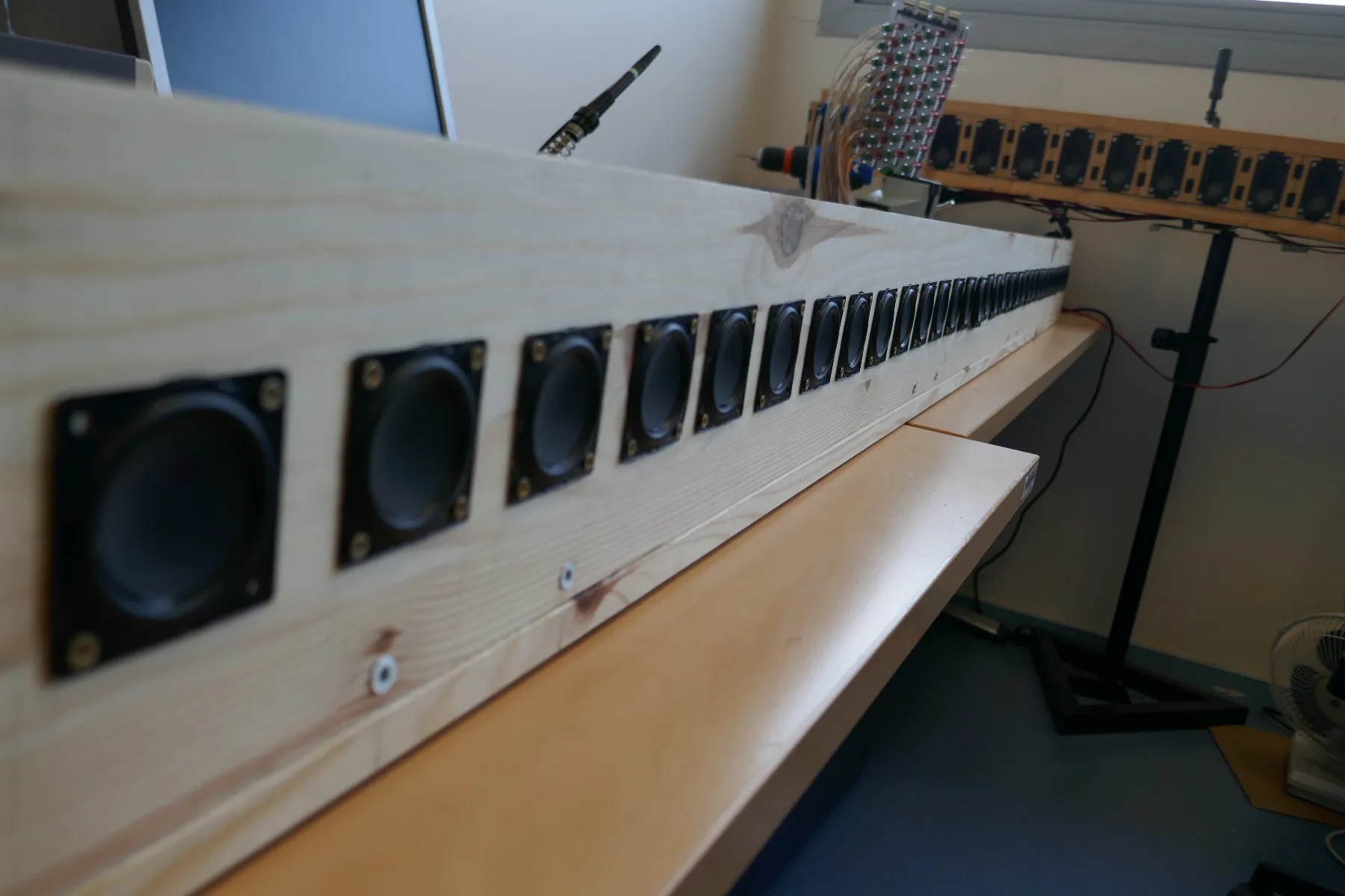
The first bar: 32 oval drivers on a wooden beam. 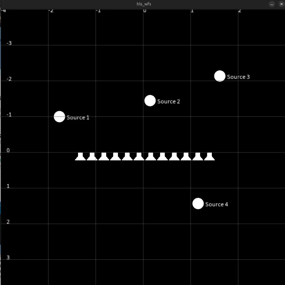
The very first control interface: sources placed in a top view around the speaker line. Second version
A second bar with the Emeraude team, with compact square drivers in place of the oval ones. Read the paper
The second version, with the first bar in the background. The Line
The Line at NIME 2026, with the Emeraude team: daisy-chained 8-channel speaker boards driven by one Zynq FPGA, tested with 64 speakers. Read the paper
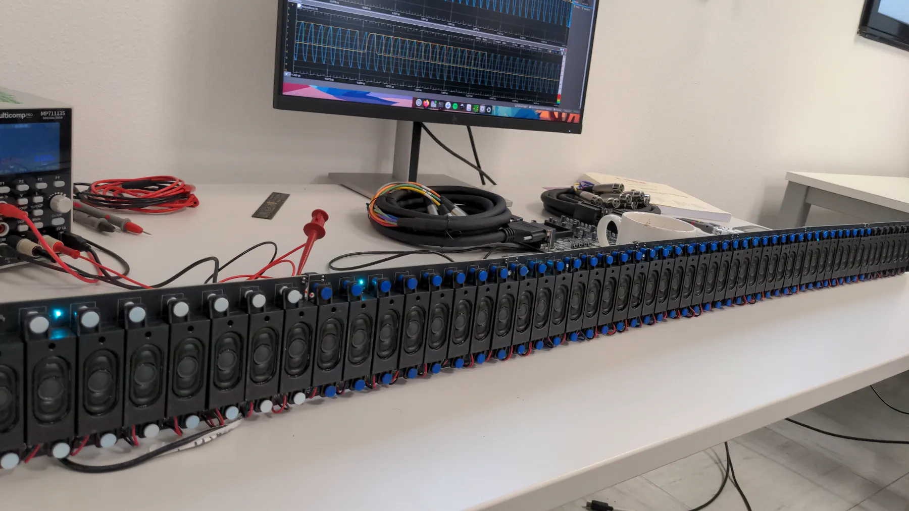
The Line: chained speaker boards on the test bench. Work starts on a commercial version
Driver characterisation starts.
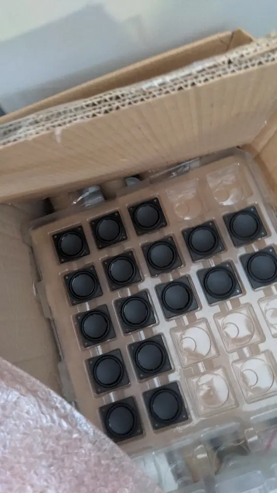
Drivers unboxed for characterisation. Design studies
A module that can be arranged into whatever a space calls for: a straight bar, a curved array, stacked rows or a full matrix. In parallel, the control board and a first control software.
Early module design, square drivers. 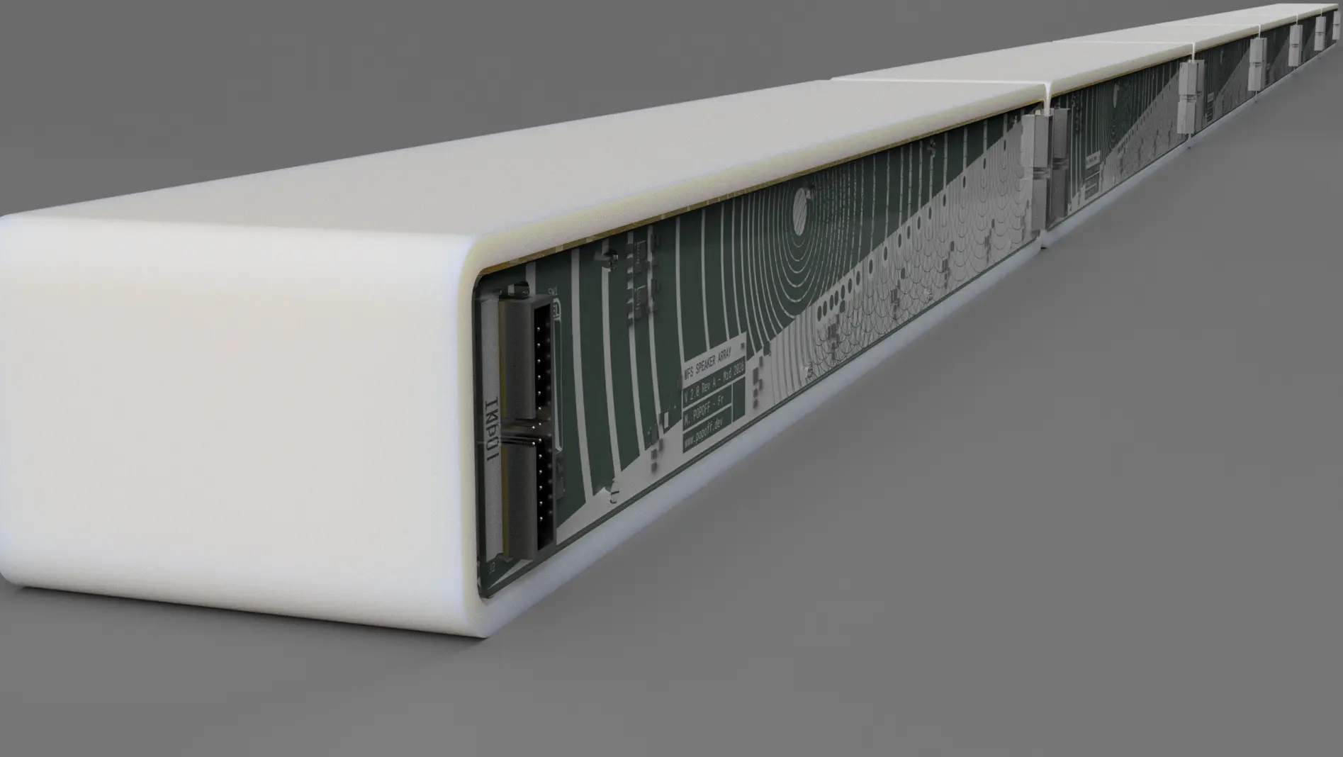
Daisy-chained modules over a single connector: one continuous array. 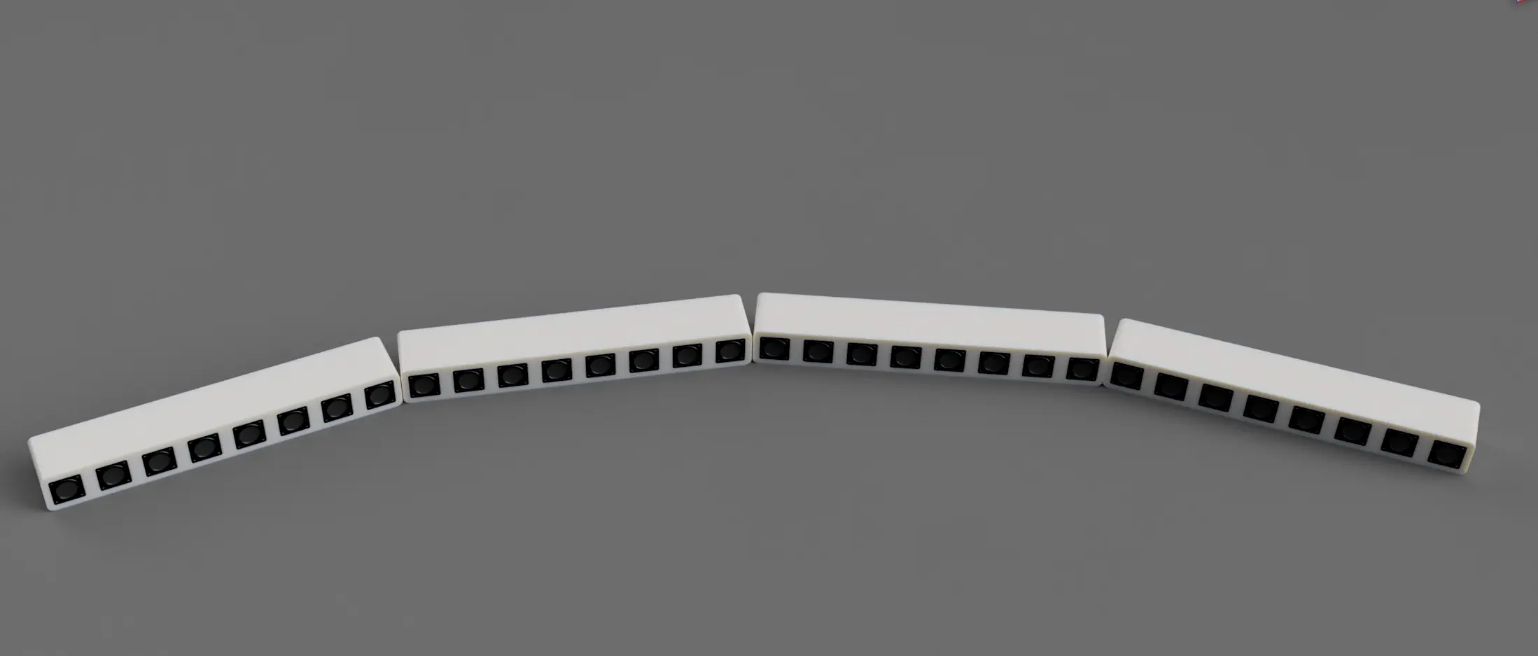
Convex bar: wider horizontal coverage for open spaces. 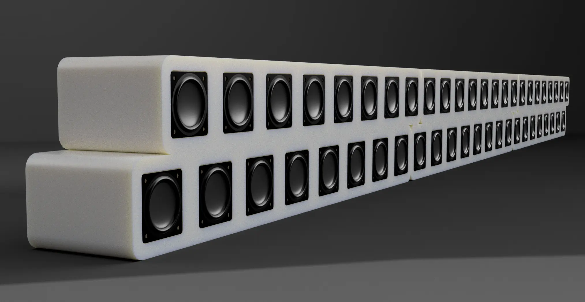
Double-height bar: staggered rows roughly double the driver density. 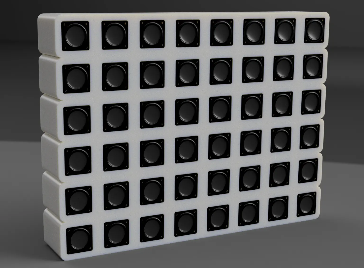
Vertical matrix: stacked rows extend positioning into the vertical plane. 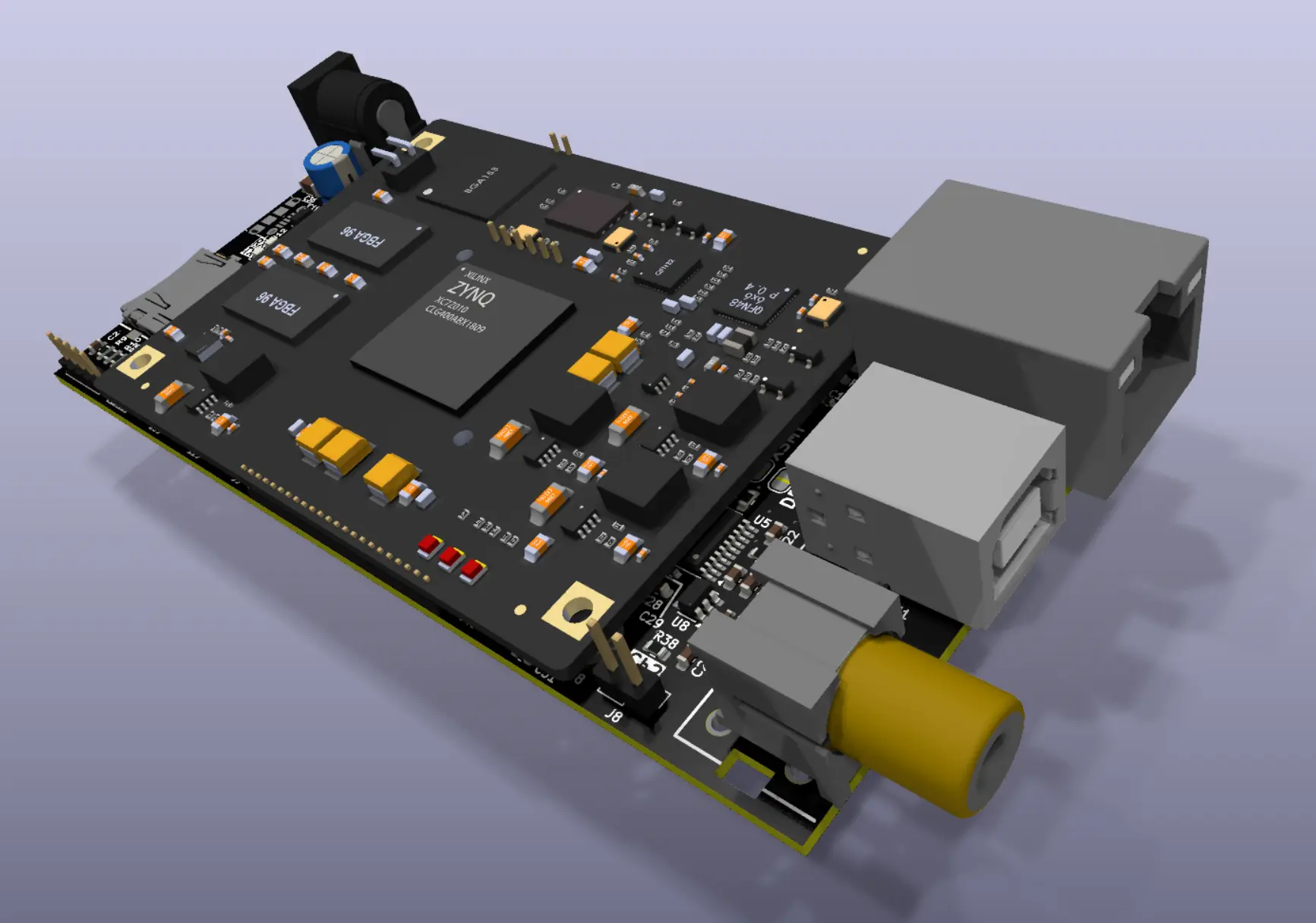
Control board render: Xilinx Zynq SoC, with USB, Ethernet and audio I/O on board. 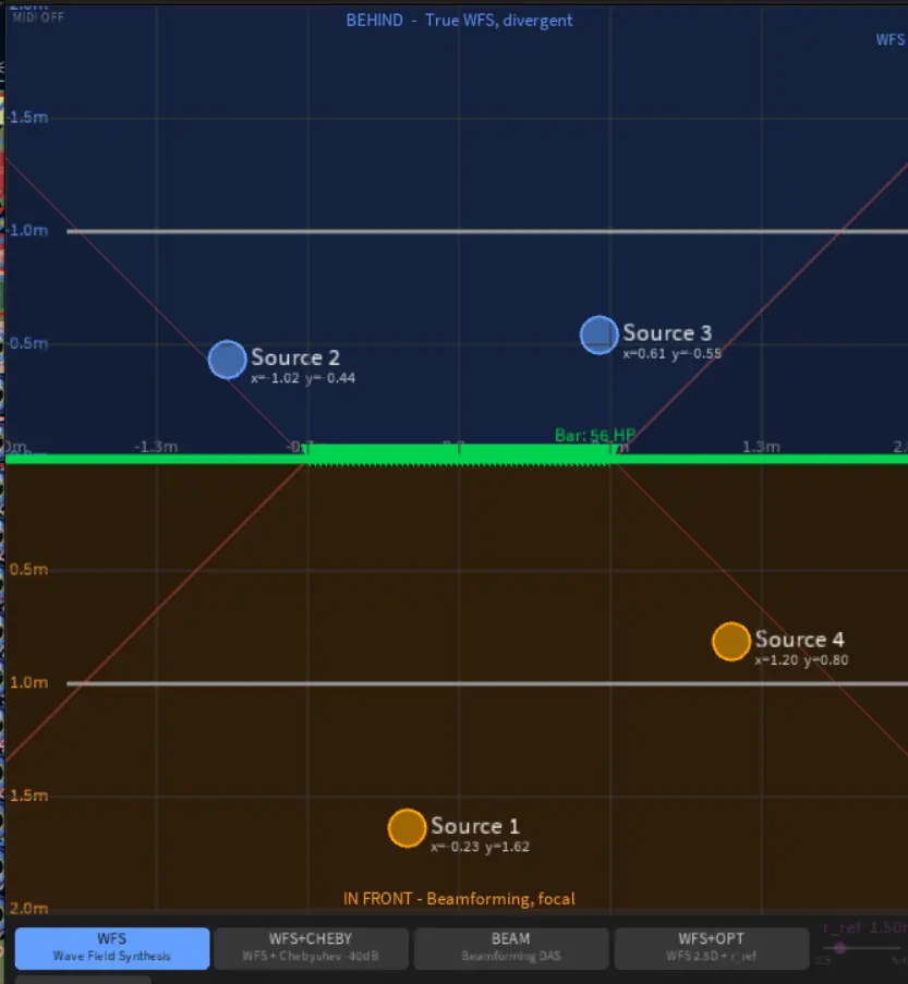
Early control software: placing sources, switching between WFS, beamforming and hybrid modes. Wooden enclosures
Enclosures CNC-routed from wood, backplates laser-cut, then sanded and assembled by hand. The first full bar then ran on The Line board.
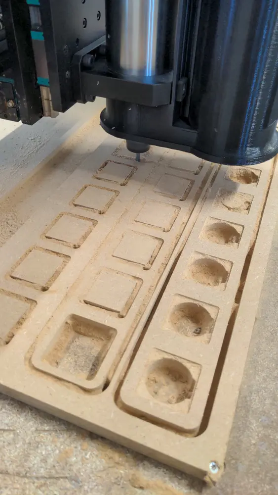
CNC routing the enclosure profile. 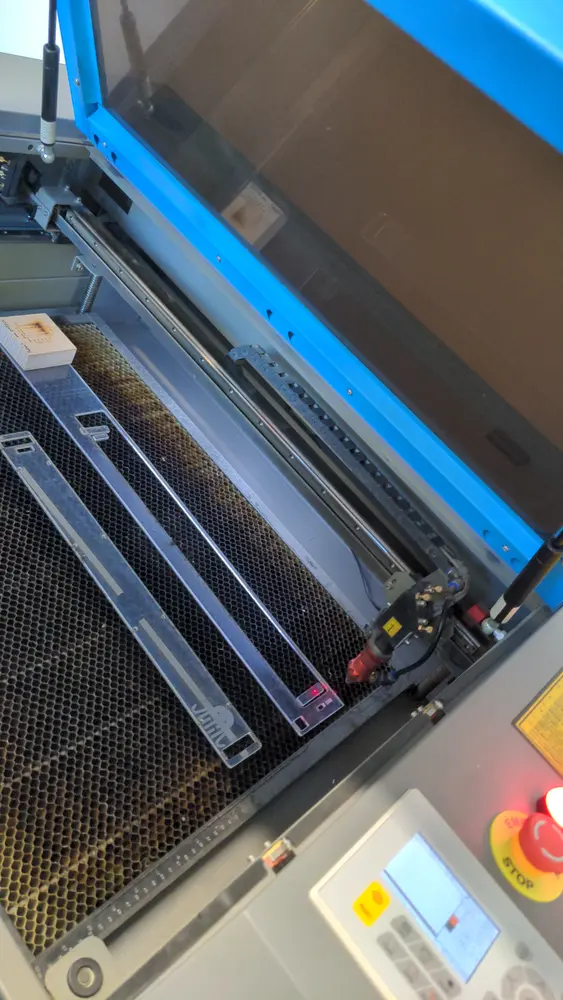
Laser cutter used for the backplate. 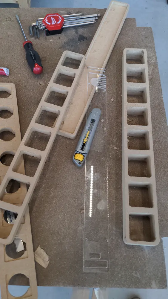
Assembly in progress. 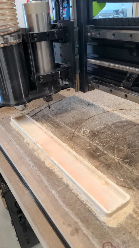
CNC routing pass, second setup. 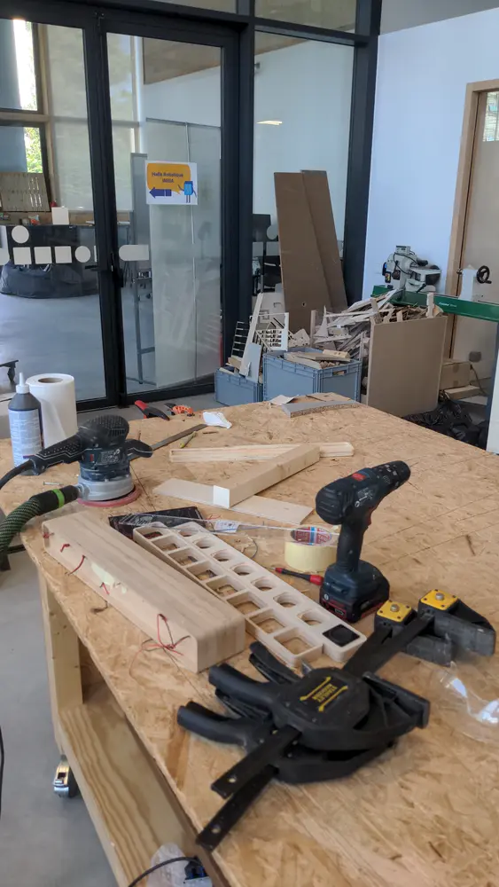
Wood parts and enclosure assembly. 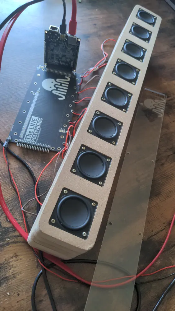
First full bar, wired to The Line board. First measurements
The wooden bar measured with a microphone, driven by The Line board.
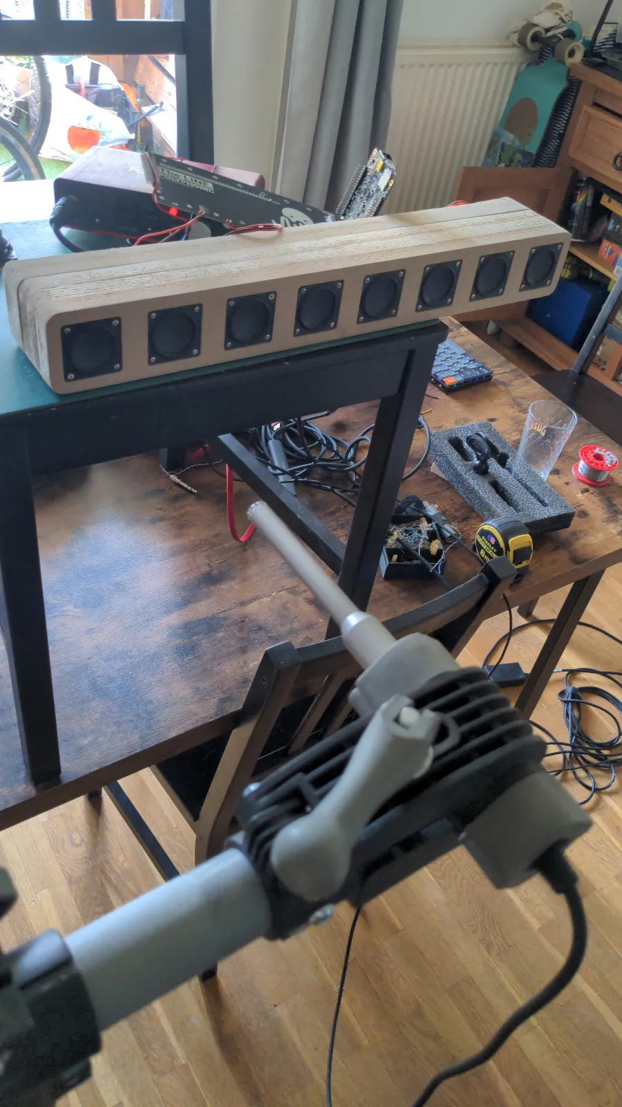
Measurement microphone facing the wooden bar. Choosing the driver
Finding the right driver took several months of tests. Different models were mounted on the same bar and measured side by side, to keep the one best suited to the array.
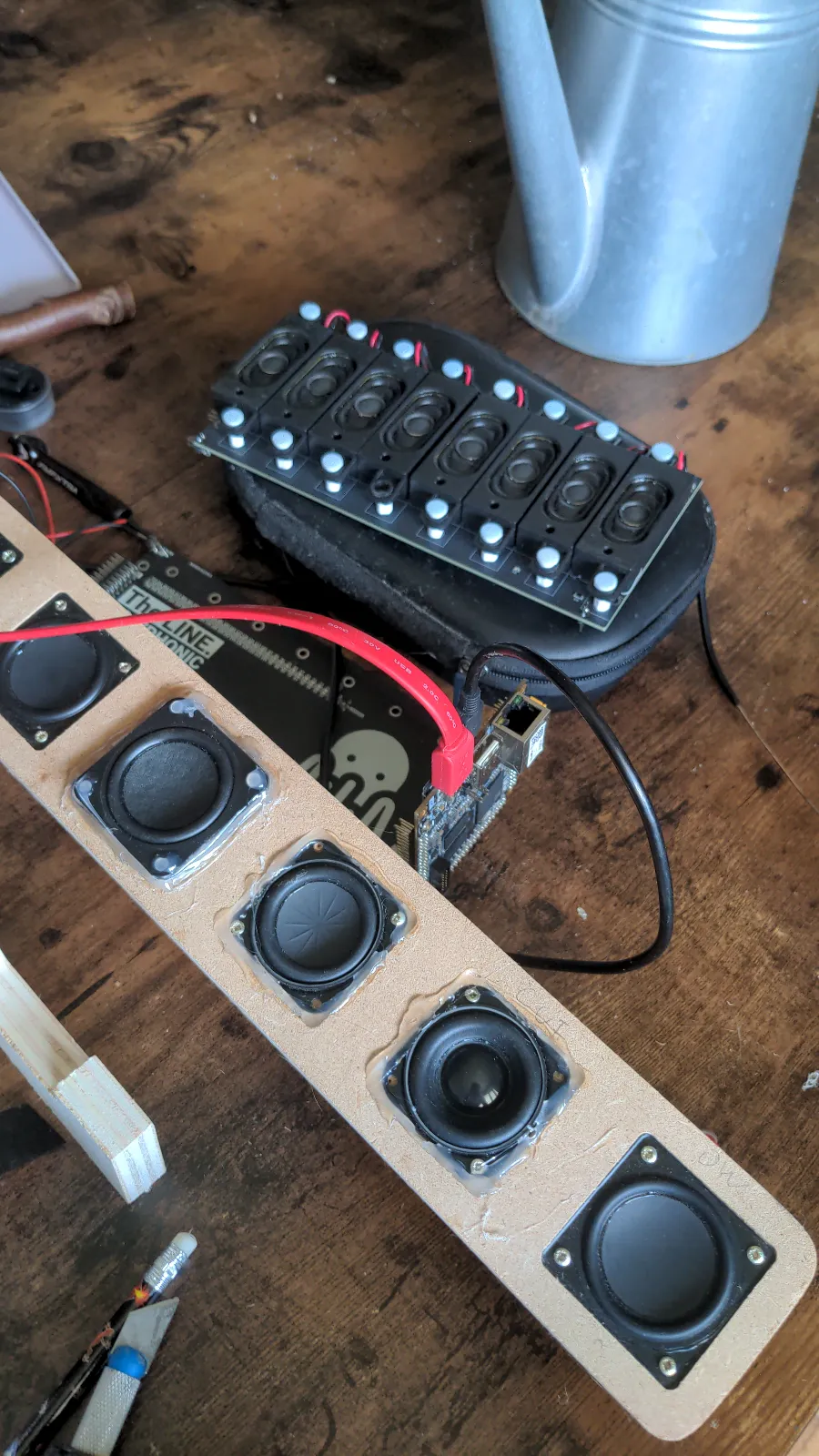
Different drivers mounted on one test bar. v1.1: 50 mm spacing
Version 1.1 brings the drivers closer together: 50 mm between drivers instead of 64 mm. The bar gets shorter and easier to carry, and the denser spacing raises the frequency up to which positions stay sharp.
From wood to 3D printing
Wood turned out too porous and too fragile for the enclosure. The bar moved to 3D printing, on a large-format printer at the fablab in Lyon.
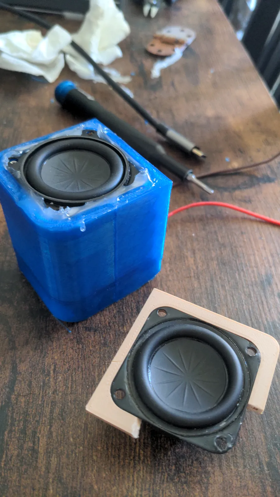
Printed test pieces: how a driver seats in a printed enclosure. 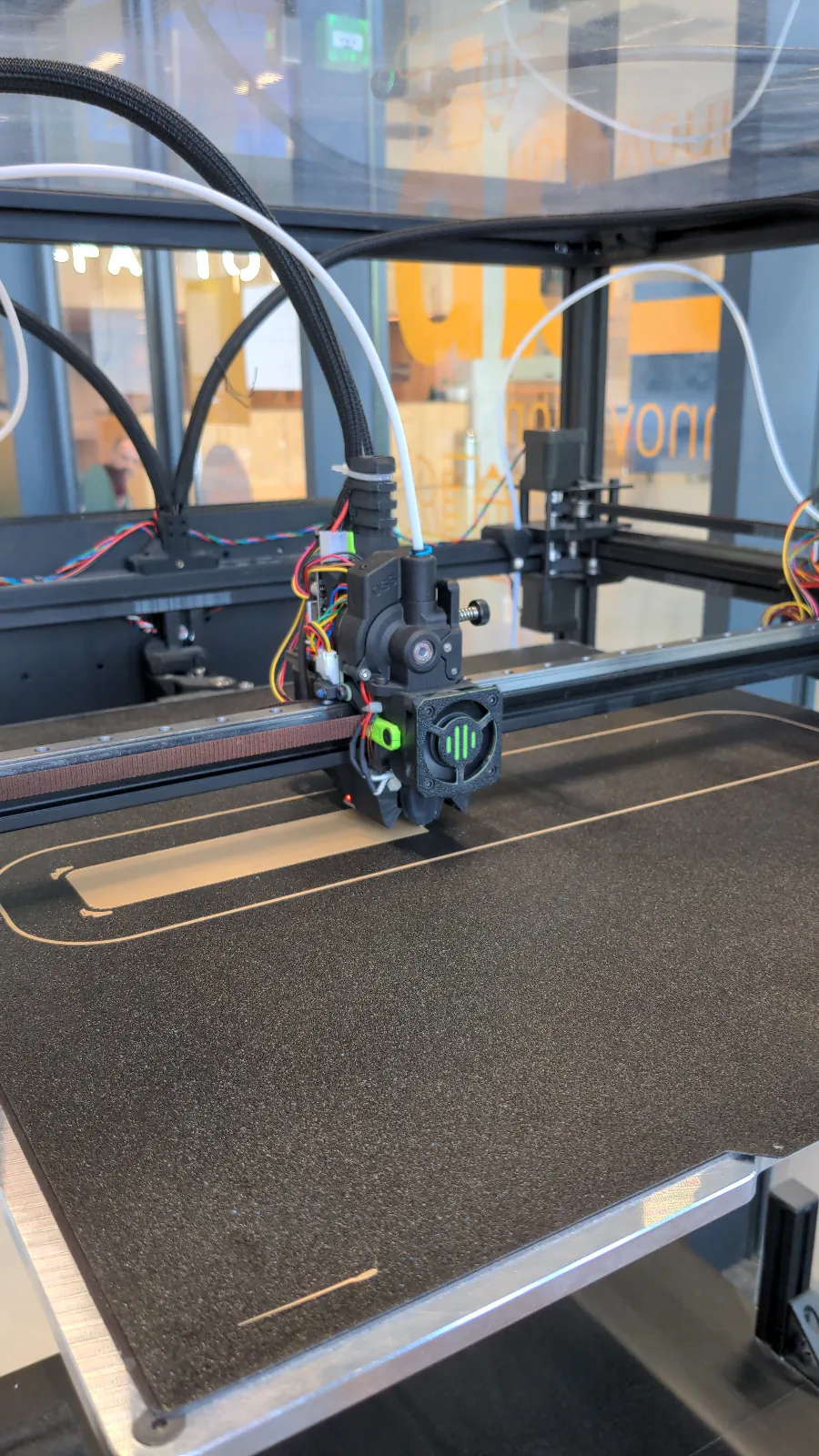
Printing a bar on the fablab's large-format printer. Timing measured
Measurements on the test bar: ±7 µs timing between drivers, across 56 drivers.
The final resin bar
The final enclosure is made of resin, in white. The prototype is complete, and OpenField opens for quotes.
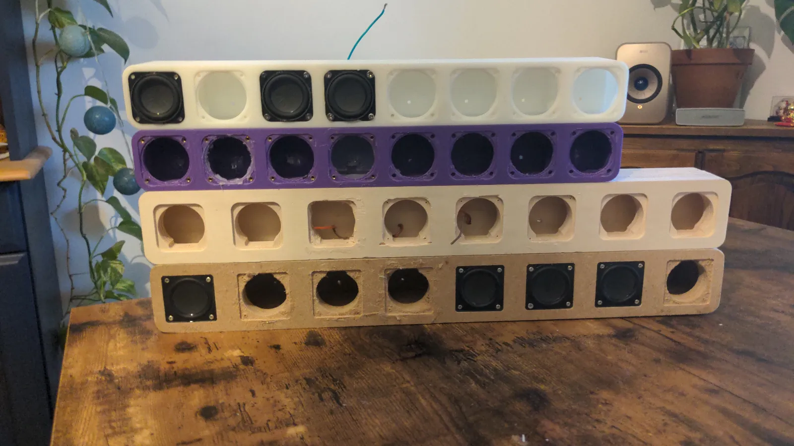
Four enclosures, bottom to top: the MDF test bar, wood, 3D print and the final resin bar. 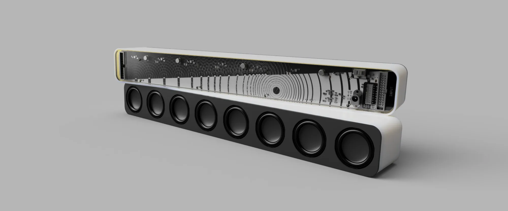
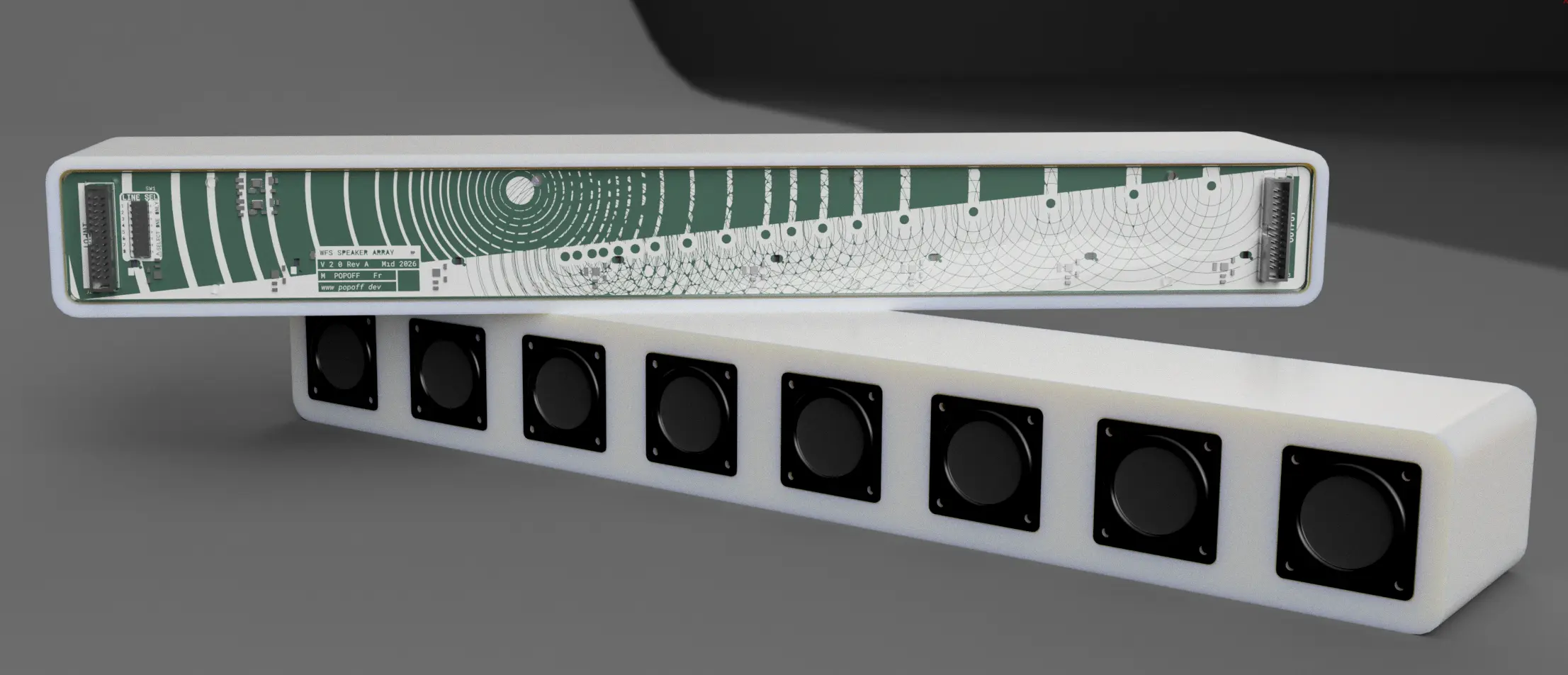
Final module: round 40 mm drivers, open back showing the speaker board. 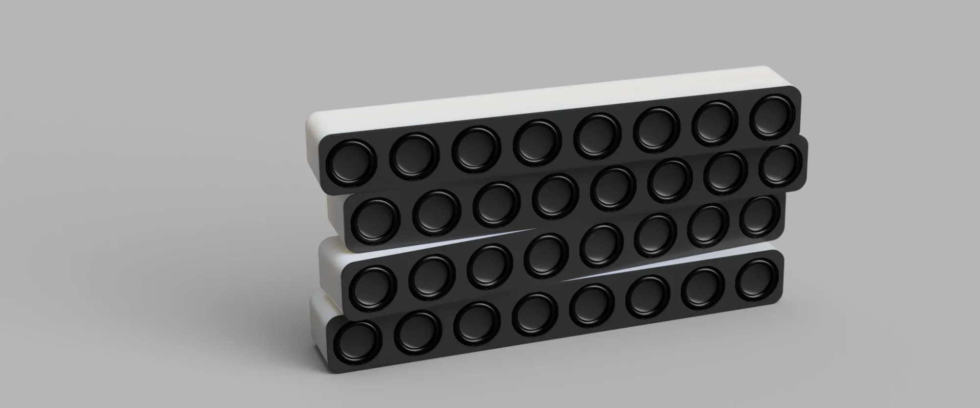
Four modules stacked for transport. Assembly of a module: back plates, speaker board and enclosure.